Very thin boundary layers and y+ on complex geometry
Don’t get discouraged, you will find a way…
I am working on a generalized procedure that might help you, this has not been validated by anyone but me yet!!!
From my personal experience so far, I believe that a good External Layered CFD Mesh, THAT USES SLIP WALLS ON THE BACKGROUND MESH BOX ‘TUNNEL’, can be achieved with the following elements:
-
Decide on the Level 0 grid mesh size. In my case my 1/2 wingspan geometry (the geometry file is the full aircraft but the simulation will be symmetrical about the fuselage center-line so all geometry bounds here are with respect to the 1/2 geometry) is about 3 meters wide, 4 meters long and 3 meters high. I chose a Level 0 grid size of 1.28 meters since Level 8 would be 0.005 meters (a good number to commit to memory). This 1.28m grid size seems to work for me and could maybe be generalized to about 1/4 of the longest geometry bounds.
-
Decide on what turbulence model to use and its initial values. From what I can determine, the best turbulence model to use for incompressible simulations and which SimScale has available is the k-omega SST model. Dylan has provided a very nice set of formulas which I am showing here that made it very easy to set initial turbulence values and to determine a good reference length for the simulation. Here is an image of my spreadsheet that shows the yellow inputs, green outputs, formulas used and a link to their sources:
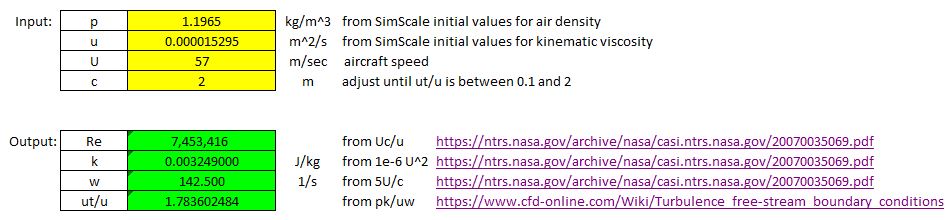
- For CFD aircraft use, the last input to enter would be reference length ‘c’ and you simply set ‘c’ to a value that makes ut/u in the range of 0.1 to 2. Since my input of 57 mps for speed is at the high end of my analysis range for this geometry I chose to keep ut/u closer to 2 at 57mps. This resulted in a need for a 2 meter reference length. _
-
Decide on what yPlus value the mesh will be analyzed at. This will determine the optimum thickness of the boundary layer cell nearest the geometry surface (the ‘estimated wall thickness’ or EWD from the online yPlus calculator). EWD mostly varies based on aircraft speed, reference length and desired yPlus of the simulation. I have learned that unless using ‘full resolution’ wall treatment in the simulations boundary conditions, it is recommended to target a yPlus of 30 to 300 (or an average of 165). I have been using a desired yPlus of 50 lately. I have read that yPlus values from 1 to 30 are just as good as 30 for results accuracy. Areas of yPlus from 1 to 30 simply means your mesh has more refinement than truly needed in that area (from the Q&A section of a tutorial video I watched, can provide this reference if needed).The aircraft speed you need is the easiest decision to be made. The reference length is another story on which very little guidance has been written. I have decided that it is likely best to use that same reference length for yPlus calculations as for the turbulence initial value calculations of item 2 above.
-
Create a Background Mesh Box (BB for short) that is generously sized as a starting point to get the optimization process started. The final size will be optimized later. This BBorg should be larger than any intuitive size that your vast CFD knowledge would guess at. My experience says that the clearance between any axis’s maximum geometry extent and the BBorg wall of that axis for a generous sized box should be ~3 times the maximum geometry range of that axis.
Items 5 to 8 will come at some point after a 2.5% undefined error that I have discovered in BB sizing and positioning is resolved (Hint hint @jprobst )
Here is point #9 on layering:
- Create a refinement that layers your mesh. You should take your best guess based on your CFD knowledge and some research at number of layers and expansion ratio for now. We will make sure this is optimized later. I really find that relative layering gives me a better yPlus map than absolute layering. The trick was to select the correct Final Wall thickness ratio to give me my desired yPlus. You can determine the proper Final Wall thickness ratio (a good ratio to shoot for is ~0.3 to 0.4) to use based on the grid size of my Item 6 above (which is a surface refinement on all surfaces that get layered). Say you want a final layer of 0.002 meters. Also if your Item 6 surface refinement is a Level 8 grid and is 0.005 meters (from a Level 0 grid of 1.28 meters), then you use thickness of final layer ratio of 0.4.
Items 10 to 14+ will come after I am able to address the 2.5% undefined error mentioned above
Go HomePage: Sách Hay 24H hoặc click: Sách hay nhất mọi thời đại, Mua sách online, Bạn đắt giá bao nhiêu, Truyện cổ tích Việt Nam, Mùa xuân nho nhỏ, Tràng giang, Hịch tướng sĩ
Học phí Đại học FPT 2025 chính thức
Học phí Đại học FPT 2025 chính thức
Hoạt động 4 trang 75 Toán lớp 6 Tập 2 - Kết nối tri thức
Hoạt động 4 trang 75 Toán lớp 6 Tập 2 - Kết nối tri thức

Tổng hợp kiến thức toán 8 học kì 1 và 2 có file PDF tải về
Tổng hợp kiến thức toán 8 học kì 1 và 2 có file PDF tải về
Soạn bài Xem người ta kìa - Ngắn nhất Kết nối tri thức
Soạn bài Xem người ta kìa - Ngắn nhất Kết nối tri thức

Cảnh giác với tình trạng chấn thương đầu của trẻ do té ngã
Cảnh giác với tình trạng chấn thương đầu của trẻ do té ngã
Hoành độ giao điểm là gì? Phương trình hoành độ giao điểm chi tiết
Hoành độ giao điểm là gì? Phương trình hoành độ giao điểm chi tiết

Soạn bài Dương phụ hành Kết nối tri thức Ngữ văn lớp 11 trang 107 sách Kết nối tri thức tập 1
Soạn bài Dương phụ hành Kết nối tri thức Ngữ văn lớp 11 trang 107 sách Kết...
Đóng vai người lính kể lại bài thơ Đồng chí của Chính Hữu điểm cao
Đóng vai người lính kể lại bài thơ Đồng chí của Chính Hữu điểm cao

Xéo xắt hay Xéo sắc? Từ nào mới đúng để chỉ sự chua ngoa?
Xéo xắt hay Xéo sắc? Từ nào mới đúng để chỉ sự chua ngoa?

Review xem nhiều


")

